17 Jun HDR Insights Article 3: Understanding HDR Tone Mapping
06/17/2019 HDR Insights Article 3: Understanding HDR Tone Mapping

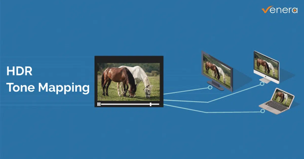
In the previous article – HDR Transfer Functions, we discussed the transfer functions and how digital images are converted to light levels for display. This article discusses how the same HDR image can be displayed differently by different HDR devices.
What is HDR Tone Mapping?
Tone mapping is the process of adapting digital signals to appropriate light levels based on the HDR meta-data. This process is not simply applying the EOTF (Electro-Optical Transfer Function) on the image data but it is rather trying to map the image data with the display device capabilities using meta-data information. Since a broad range of HDR display devices are available in the market, each with their own Nits (i.e. ‘brightness’) range, correct tone mapping is necessary for a good user experience. Since the tone mapping is done based on the meta-data in the video stream, presence of correct meta-data is necessary.
Source footage can be shot at HDR with best of cameras and then mastered on high-end HDR mastering systems, but it still need to be displayed optimally on the range of HDR televisions available in the market. Tone mapping performs an appropriate brightness mapping of the content to device without significant degradation.
Need for HDR Tone Mapping
Let’s say an image is shot with peak brightness of 2000 Nits. If it is displayed on a television with 0-2000 Nits range, the brightness range will be exactly as shot in the raw footage. However, the results will be different on other devices:

Since tone mapping is a necessary operation to display PQ based HDR content on HDR display devices, the television needs to know the native properties of the content in terms of the brightness range used along with mastering system parameters. This information is conveyed in the form of HDR meta-data. After reading the HDR meta-data, display devices can decide the tone mapping parameters so that the transformed video lies optimally within the display range of the display device.
Next article will discuss the specific meta-data for HDR-10 and HDR-10+, two different implementation of the HDR. Stay tuned for that.
Article 2: Transfer functions
Definitions
cd/m2 – The candela (cd) is the base unit of luminous intensity in the International System of Units (SI); that is, luminous power per unit solid angle emitted by a point light source in a particular direction. A common wax candle emits light with a luminous intensity of roughly one candela.
Nits – A non-SI unit used to describe the luminance. 1 Nit = 1 cd/m2.
HDR – High Dynamic range. It is a technology that improves the brightness & contrast range in an image (upto 10,000 cd/m2)
SDR – Standard Dynamic range. It refers to the brightness/contrast range that is usually available in regular, non-HDR televisions usually with range of upto 100 cd/m2. This term came into existence after HDR was introduced
WCG – Wide Color Gamut. Color gamut that offer a wider range of colors than BT.709. DCI-P3 and BT.2020 are examples of WCG offering more realistic representation of images on display devices.
EOTF – electo-optical transfer function. A mathematical transfer function that describes how digital values will be converted to light on a display device.
OETF – optical-electro transfer function. A mathematical transfer function that describes how the light values will be converted to digital values typically within cameras.
OOTF – opto-optical transfer function. This transfer function compensates for the difference in tonal perception between the environment of the camera and that of the display.
PQ – PQ (or Perceptual Quantizer) is a transfer function devised to represent the wide brightness range (upto 10,000 Nits) in HDR devices.
HLG – HLG (or Hybrid Log Gamma) is a transfer function devised to represent the wide brightness range in HDR devices. HLG is quite compatible with existing SDR devices in the SDR range.